All-Wheel Drive mod
This component is in alpha state.
This modification to the FLSUN Super Racer changes the A/B/C axis configuration by extending it to two active motors per axis and swapping the motion parts for a more durable option.
Required materials
Bolts and other fasteners
| Size | Type | Amoun | Stores |
|---|---|---|---|
| M3x8 | 12 | … |
Motion components
| Type | Variant | Amount | Unit | Stores |
|---|---|---|---|---|
| Open timing belt | GT2 10mm | 6 | meter | |
| Motor pulley | GT2 5mm for 10mm belt 20T or | 6 | piece | Mellow |
| or | 6 | piece | Powge | |
| or | 6 | piece | Kis-3D | |
| Stepper motor | LDO 42STH48-2504AC-R or | 6 | piece | |
| Stepper motor | LDO 42STH48-2504AC or | 6 | piece | |
| Stepper motor | E3D High Torque 0.9° | 6 | piece |
Electronics
| Type | Variant | Amount | Unit | Stores |
|---|---|---|---|---|
| Stepper cable | 3 | piece | ||
| Controller | See the options below | 1 | piece |
Controller expandsion (option 1)
The FLSUN Super Racer comes with either a BTT SKR v1.3, or an MKS Robin Nano V3 controller board. Both of these boards can be extended over the EXP1/EXP2 ports with an affordible BTT EXP-MOT extension board. This option is recommended for the budget concious builds.
| Type | Variant | Amount | Stores |
|---|---|---|---|
| Controller | BTT EXP-MOT [^1] | 1 | BigTreeTech |
| Driver | TMC2209 [^1] | 3 | BigTreeTech |
| Fysetc | |||
| Mellow |
Optional materials
Linear rails
Replacing the linear rails is completely optional and may not be required if the stock rails run smoothly!
| Size | Type | Amount | Stores |
|---|---|---|---|
| 600mm | 3 | CNA | |
| 3 | Usongshine |
Required tools
| Type | Variant | Amount | Unit | Stores |
|---|---|---|---|---|
| Center punch | Any | 1 | piece | For marking the holes in the printed template |
| Drill | Electric | 1 | piece | High RPM for drilling through aluminium |
| Drill bit | 1 | piece | Suitable for drilling alumium | |
| Tape | Any | 3 | piece | Easy to remove tape to prevent burring |
Printed parts
| File | Amount | Description |
|---|---|---|
| sr_awd_jig.stl | 3 | Bottom motor mounting plate, use a heat resistent plastic like ASA or PC(CF) |
Making the required hardware modifications
Adding the AWD motors
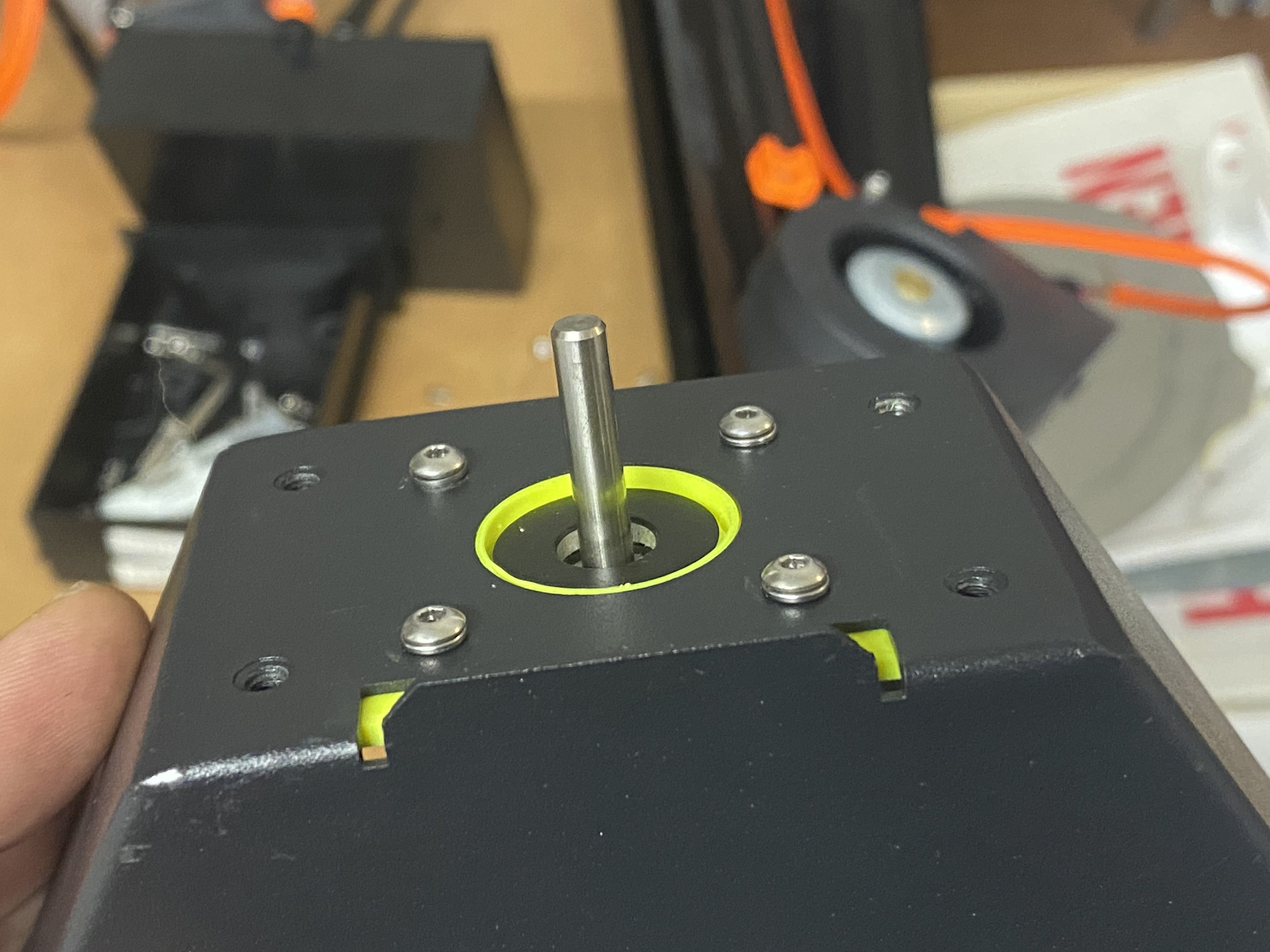
Start off by printing the AWD jigs, you will need them for aligning the mounting holes, as well as aligning the motor in the already existing hole. Remove the bottom part of the printer by detaching the power cable going to the top electronics bay, continue by removing the 4 M5x12mm screws from the columns. The base of the printer should be free now. Continue with removing the bottom lid button head screws until you have access to the bottom bay:
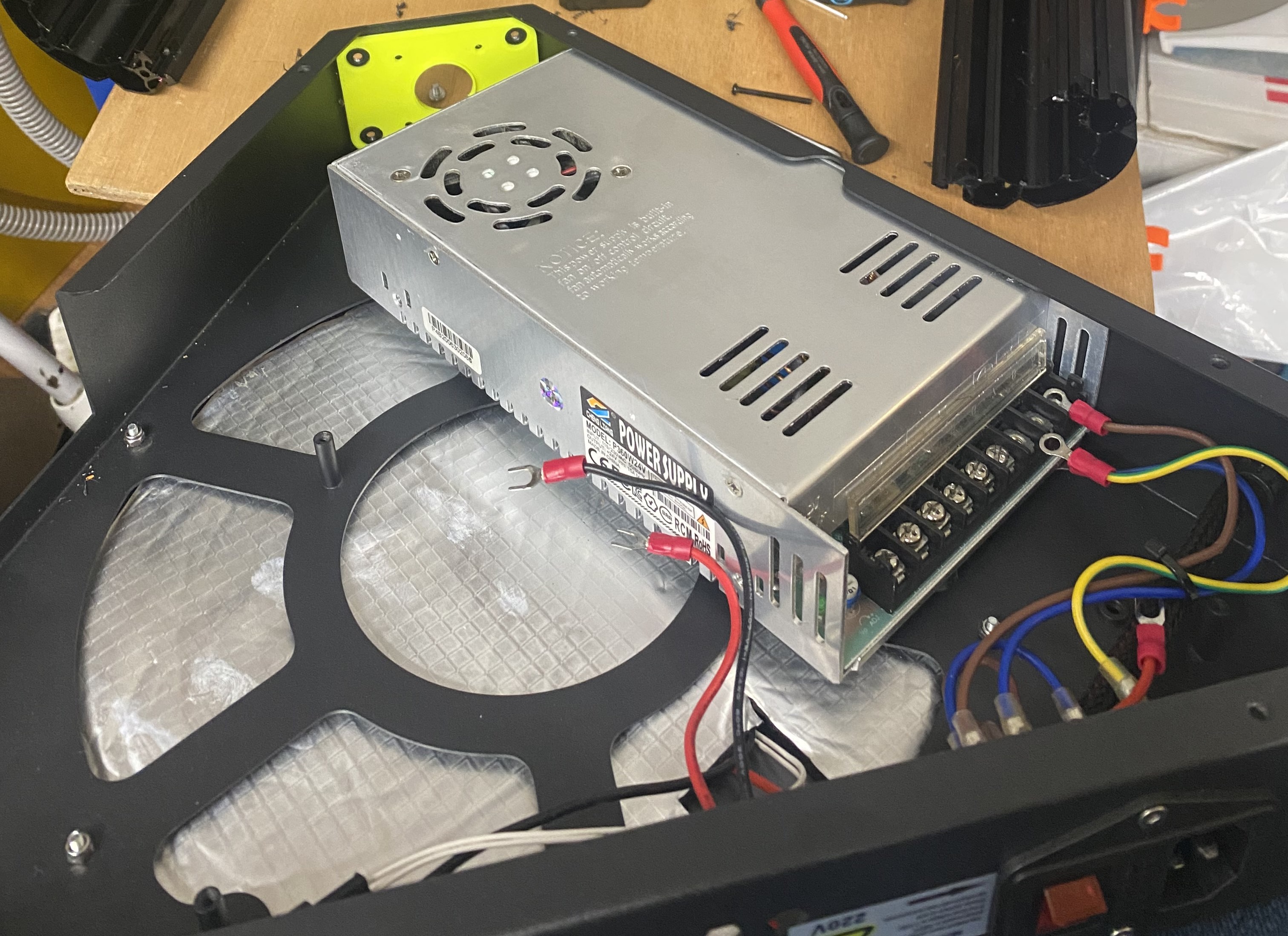
The drill jig fits nicely against the spacers inside the frame. Do mind that you may have to remove the vertical post that the mains wiring is attached to, using pliers is probably sufficient as the weld isn’t super strong. If you are afraid of damaging the case, use a rotary cut tool or a hacksaw. Before you start drilling make sure to remove the power supply from the case and disconnect all the wiring. Transfer the holes with the jig using a center punch, then continue drilling the four holes for each of the motor positions.
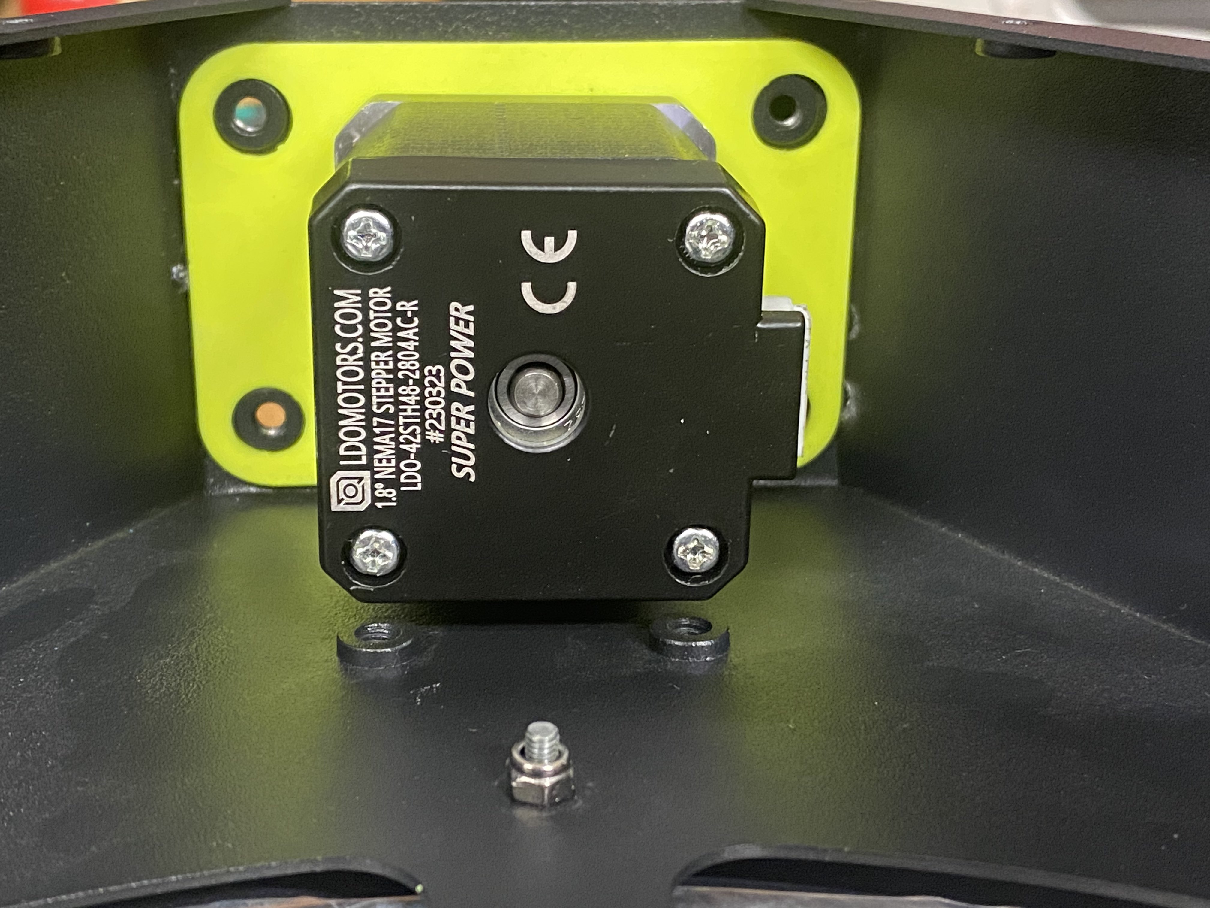
Once the holes are drilled, you can screw down the motor using the M3x8mm bolts. It is advised to add M3 washers between the bolts and the holes.
Adding the AWD belt
Soon! ™